Mechanical
The mechanical documentation involves designing, 3D printing and assembling the PiCar chassis
Caution
The mechanical design and assembly of the PiCar will continue being modified over the course of the research. The following guide reflects the earliest version of PiCar v2.0.
Design
For the base chassis of PiCar v2, we will be using the Dromida 1/18 Scale
Buggy. To retrofit it with sensors and micro-controllers, we will be adding
some 3D printed parts.
CAD
The parts are designed using Autodesk Fusion 360. We will be splitting the chassis into three layers, connected with spacers for better management:
- Layer Zero
- Dromida buggy (without cover)
- DC Motor (drive)
- Servo (steer)
- Encoder
- ESC (Electronic Speed Controller)
- Layer One
- Raspberry Pi
- Arduino
- Lipo Battery(s)
- Current sensors
- IMU (Intertial Measurement Unit)
- Layer Two
- Servo (LIDAR)
- TFMini LIDAR
- PiCamera
Materials Required
Warning
The 7.4V LiPo battery must be used with care. Use a voltmeter or battery checker to ensure that the battery voltage does not drop below 30%.
Note
If the 48P 20T 4mm bore Pinion Gear cannot be found, buy a 48P 20T Pinion
Gear and use a drill to create a 4mm bore (shaft diamater).
Assembly
Tools Required:
- Dremel kit (with drill and sanding bits)
- Screw drivers
- Pliers
- Download the Fusion 360 CAD files, convert them to STL and 3D print them.
- Encoder Mount: https://a360.co/2DUNNK6
- First Layer: https://a360.co/2RquoDs
- Second Layer: https://a360.co/2OBMGmP
- Camera: https://a360.co/2QQB4dp
- For PiCar v2.0, the
Dromida 1/18th Scale Buggywas used:
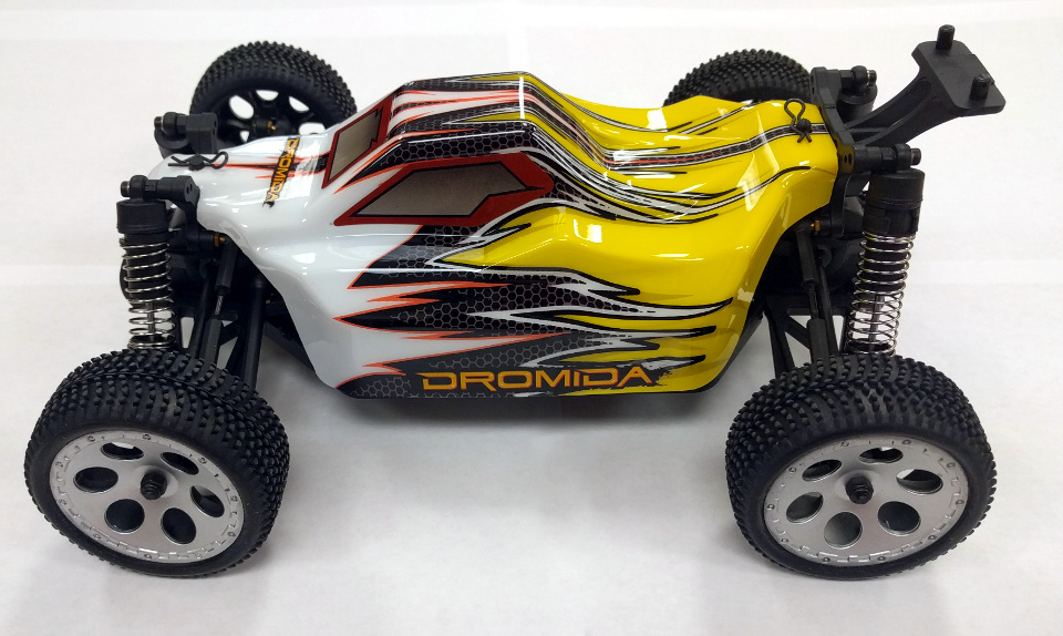
Dromida 1/18th Scale Buggy
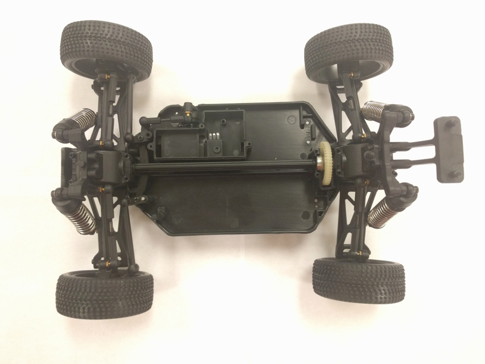
3. Remove the plastic covering and unplug the NiMh battery.
We will be using a LiPo battery to power the PiCar.
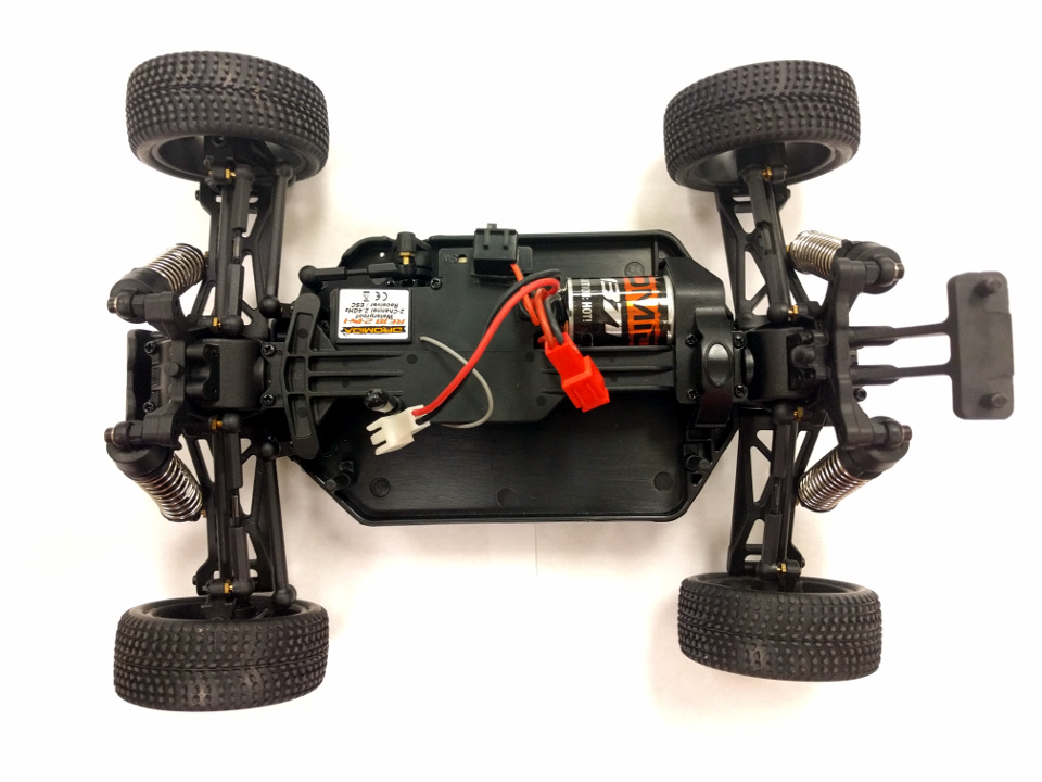
Buggy with plastic casing and battery removed
4. Unscrew, and remove the rear gear covering and the plastic spline that goes along the center of the car.
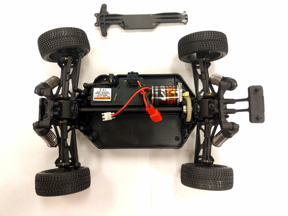
Rear gear covering and spine removed
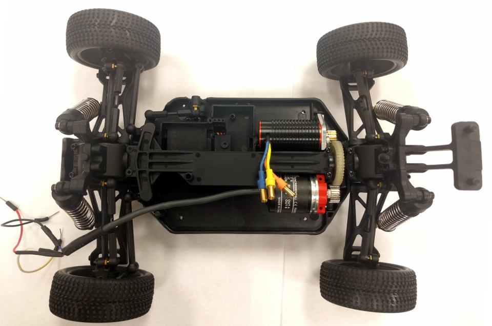
5. Unscrew the plastic cover for the ESC (Electronic Speed Controller).
Unplug the motor and servo connectors from the ESC. Remove the motor from
the car. Do not remove the servo.
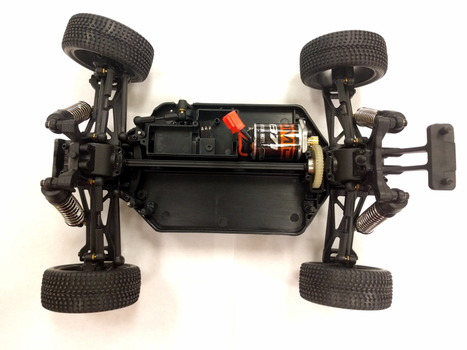
ESC removed
6. Unscrew the metallic motor mount. Pull out the plastic ‘pillar’ on the left of the rear gear.
Motor removed
7. Since we are using a rotary encoder for the low level speed controller,
we need to ensure that the encoder meshes with the rear gear. Using the dremel
and a sanding tool, carefully clear away the plastic from the gear as shown.
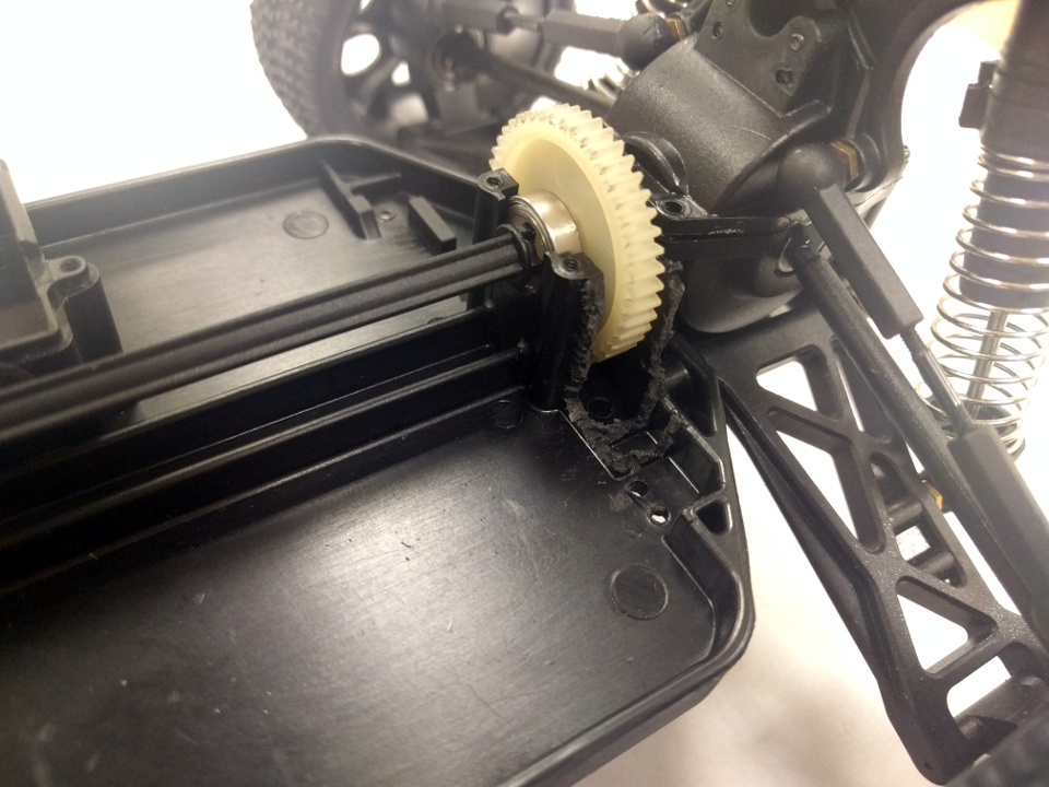
Plastic cleared away for meshing Encoder
Ensure that the encoder with its pinion gear meshes with the rear gear
and is not blocked by the plastic casing.
8. Screw in the printed encoder mount to the encoder and place it
on the chassis as shown in the figure:
Placed the encoder
Ensure that the rear gear rotates along with the encoder gear with little
to no friction. Holding the encoder in place, using a long narrow tipped
screwdriver or nail or drill-bit, mark where the mounting holes would go.
Drill 2mm holes in those points and mount the encoder either by using screws
on the bottom of the chassis (recommened), or from the top.
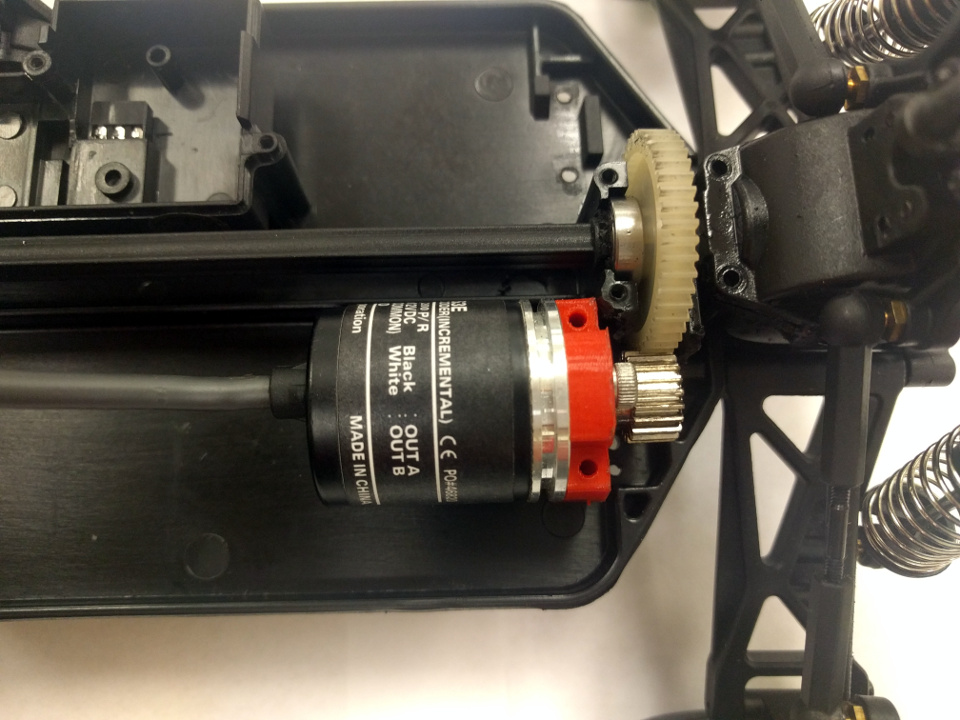
9. Replace the Dromida motor with the TrackStar Motor. Screw the motor
mount back in.
Replaced the default motor with the TrackStar motor.
10. Now we are going to begin adding the layers that hold the electronics. Drill 2mm holes as specified in the following figure:
Drilled holes to mount the first printed layer
Note
It may be more convenient to use the corner mounting holes as a guide to mark the locations of the holes on the base.
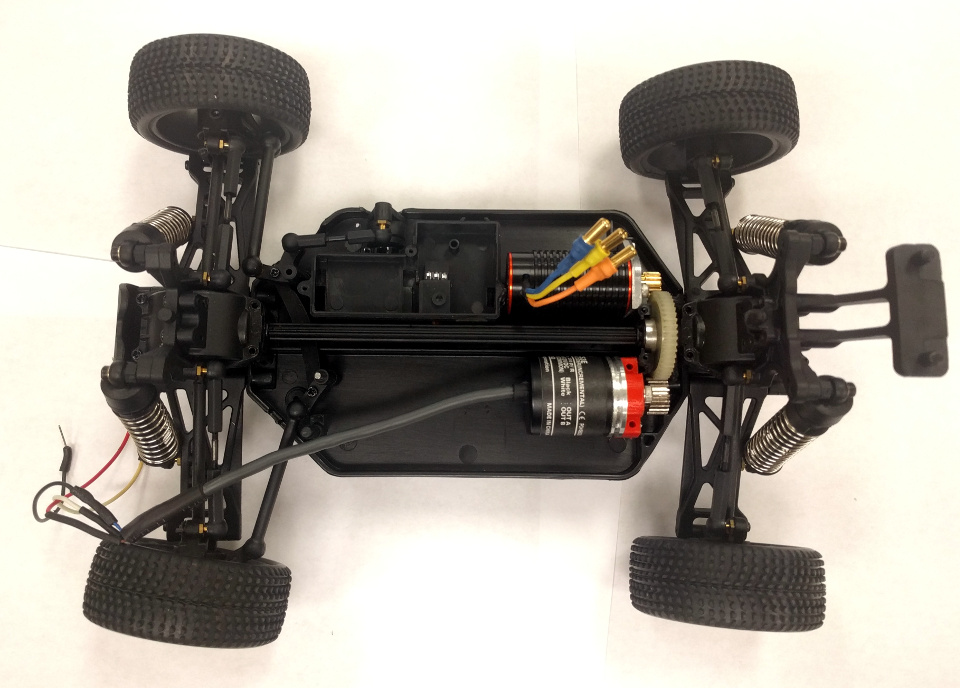
11. Connect the TrackStar ESC to the motor using the color coded wires.
Reattach the spine:
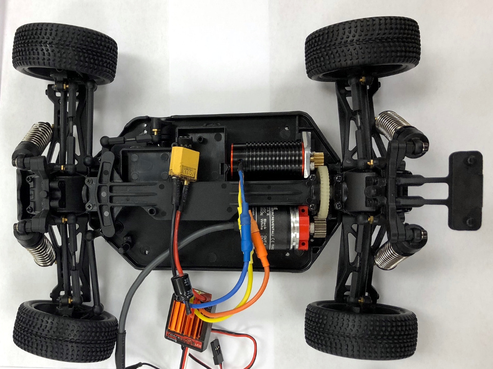
ESC connected
12. Before we mount the printed first layer to the car using spacers,
it may help to mount the IMU, Raspberry Pi, and the Arduino to the
first layer.
- Pre-requisites for this step:
- Create a common GND and +5V channel (we used a broken off piece from a small
breadboard) - Wire the
IMUand mount it to the first layer using a screw. - Mount the
ArduinoandRaspberry Piin their respective positions usingspacers.
- Create a common GND and +5V channel (we used a broken off piece from a small
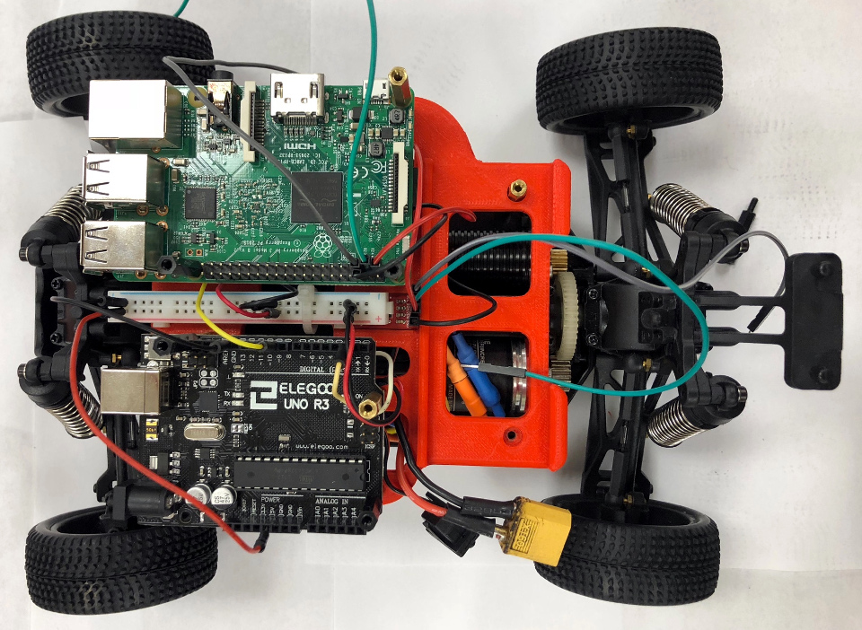
First Layer Setup
- Post-requisites for this step:
- Connect the
steering servo,ESCand theencoderto theRaspberry Piusing usage/electronics.html - Mount the
printed first layerto thechassisusingspacers(preferably metal ones)
- Connect the
- Mount the
printed second layerto the chassis using thespacers.
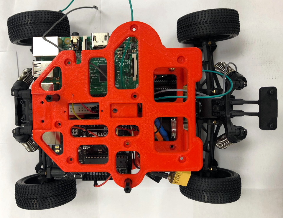
Second Layer Setup
14. Again, using usage/electronics.html as a guide, complete the electrical assembly for the second layer.
- This includes:
- Connecting a
relaythat acts as a kill switch - Connecting the SPI / I2C communication between the
Raspberry Piand theArduino - Connecting the
IMUto theRaspberry Pi
- Connecting a
Now the PiCar is usable, and should look like this:
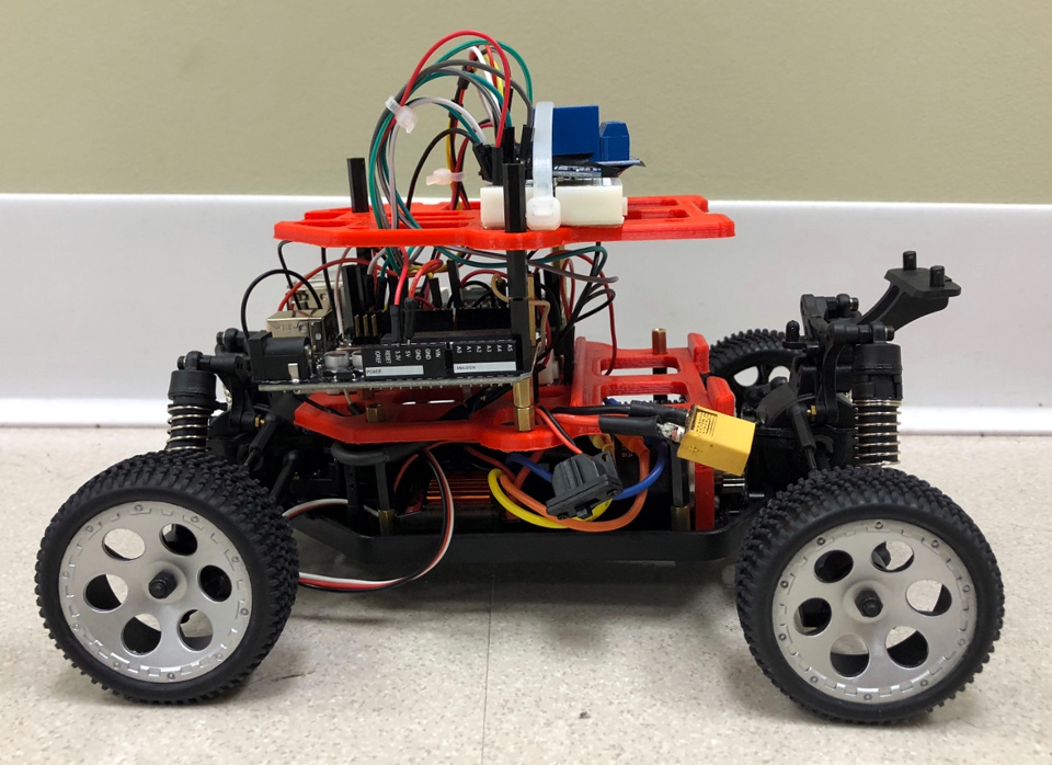
PiCar: Side View
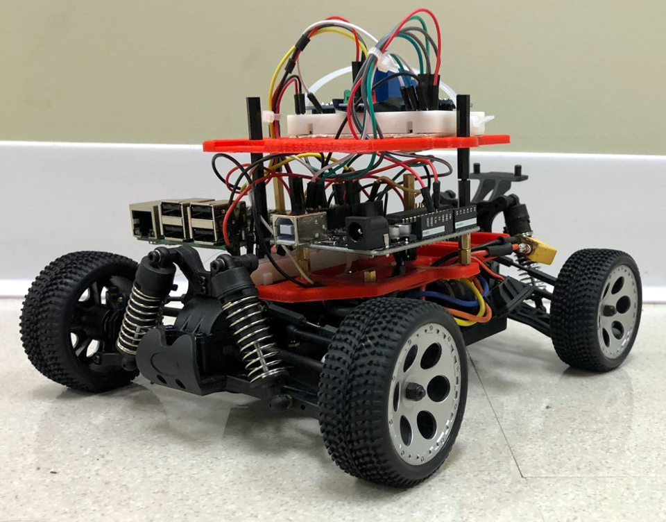
PiCar: Isometric View
15. Once the base PiCar has been built, you can add the Lidar, PiCamera,
etc. using the 3D printed mounts, and wire them accordingly.
- Ending notes:
- The
LiPo batterysits in the first layer, behind the microcontrollers. - For the time being, we are using a
compact power bankto power theRaspberry Pi, which in turn powers theArduinovia USB.
- The